For this experiment a moisture sensor is used as an analogue input and it triggers a LED which is drived by a transistor in the first experiment and by a relay on the second one. This project was great opportunity in order to examine and understand the differences between the transistor and the relay.
Furthermore with the use of a water pump instead of a LED this system can turn into an automated water planning system.
Moisture Sensor
The project’s soil moisture sensor consist of two components. A two legged front, that goes into the soil and can measure the pH of that area. This has two header pins which connect to an Amplifier/ A-D circuit which is in turn connected to the Arduino.
The Amplifier has a Vin, Gnd, Analog and Digital Data Pins. This means that you can get the values in both Analog and Digital forms.
Most soil moisture sensors are designed to estimate soil volumetric water content based on the dielectric constant (soil bulk permittivity) of the soil. The dielectric constant can be thought of as the soil’s ability to transmit electricity. The dielectric constant of soil increases as the water content of the soil increases. This response is due to the fact that the dielectric constant of water is much larger than the other soil components, including air. Thus, measurement of the dielectric constant gives a predictable estimation of water content.
What is Transistor?
A transistor is a semiconductor device used to amplify or switch electronic signals and electrical power. It is composed of semiconductor material usually with at least three terminals for connection to an external circuit. A voltage or current applied to one pair of the transistor’s terminals controls the current through another pair of terminals. Because the controlled (output) power can be higher than the controlling (input) power, a transistor can amplify a signal.
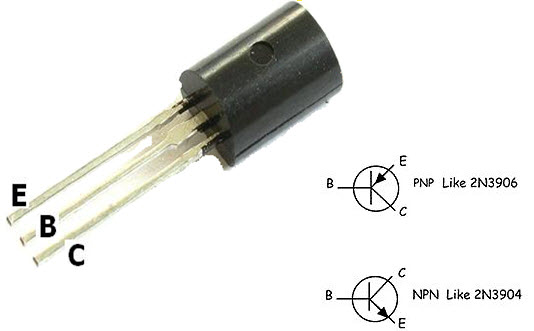
• There are two types of transistors the NPN and PNP. It can be used as amplifier as well as switch.
• The terminals of transistors are known as Base, Emitter and Collector.
• Transistor can function as switch. There are two modes in a transistor cut-off and saturation. In cut-off mode, transistor is said to be open switch. In saturation mode, it is said to be closed switch.
• In NPN, when negative DC bias voltage is applied to base, it operates in cut-off mode and when positive voltage is applied to base, it operates in saturation mode.

What is Relay?
The relay is controlled device which opens and closes contacts in order to effect operation of other devices in the same or another electric circuit.
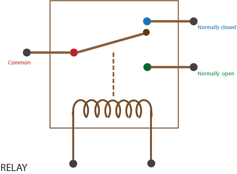
• The relay is used in circuits with lower ampere capacity i.e. Max. 20A.
• They are smaller in size.
• They have at least two NO/NC contacts.
• They are used in control circuits, automation circuits, protection circuits and switching circuits.

Differences
Relays are on-off devices. Transistors can have their voltage drop varied.
Relays are far slower than transistors; typically 50ms to switch, and probably more. Some types of transistors can switch in picoseconds (almost 10 orders of magnitude faster.)
Relays are isolated. Transistors can be (e.g. SSR), but are often not.
Relays are electromagnetic and bring problems with them – for example, try building a relay computer with many relays. You will find that relays will interfere with each other in some cases. Transistors are not very EM sensitive. They do not emit much electromagnetic interference.
Relays consume a lot of current in the “on” state, most transistors do not.
