For controlling external devices connected to Arduino, for example a robot, the user needs some form of control over the board in order to send the desired information. In this project a gamepad is used in order to control 3 different LEDs. The idea is that with the use of the same logic you can build huge projects controlling big machines just with the use of a gamepad or just a simple PC mouse.
The below figure shows the system’s block diagram. The gamepad sends the users input to the computer and through the Processing software platform which with the use of some libraries (Firmata, Gamecontrol, Serial) the information are translated into commands for the controller.
Each button corresponds to a LED. By the press of the yellow button the yellow LED turns on, by the press of the red button the red LED will light and with the green one the green LED.
For this experiment a moisture sensor is used as an analogue input and it triggers a LED which is drived by a transistor in the first experiment and by a relay on the second one. This project was great opportunity in order to examine and understand the differences between the transistor and the relay.
Furthermore with the use of a water pump instead of a LED this system can turn into an automated water planning system.
Moisture Sensor
The project’s soil moisture sensor consist of two components. A two legged front, that goes into the soil and can measure the pH of that area. This has two header pins which connect to an Amplifier/ A-D circuit which is in turn connected to the Arduino.
The Amplifier has a Vin, Gnd, Analog and Digital Data Pins.
This means that you can get the values in both Analog and Digital forms.
Most soil moisture sensors are designed to estimate soil
volumetric water content based on the dielectric constant (soil bulk
permittivity) of the soil. The dielectric constant can be thought of as the
soil’s ability to transmit electricity. The dielectric constant of soil
increases as the water content of the soil increases. This response is due to
the fact that the dielectric constant of water is much larger than the other
soil components, including air. Thus, measurement of the dielectric constant
gives a predictable estimation of water content.
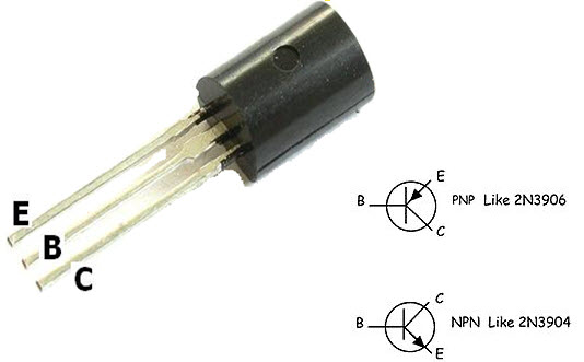
What is Transistor?
A transistor is a semiconductor device used to amplify or switch electronic signals and electrical power. It is composed of semiconductor material usually with at least three terminals for connection to an external circuit. A voltage or current applied to one pair of the transistor’s terminals controls the current through another pair of terminals. Because the controlled (output) power can be higher than the controlling (input) power, a transistor can amplify a signal.
• There are two types of transistors the NPN and PNP. It can be used as amplifier as well as switch. • The terminals of transistors are known as Base, Emitter and Collector. • Transistor can function as switch. There are two modes in a transistor cut-off and saturation. In cut-off mode, transistor is said to be open switch. In saturation mode, it is said to be closed switch. • In NPN, when negative DC bias voltage is applied to base, it operates in cut-off mode and when positive voltage is applied to base, it operates in saturation mode.
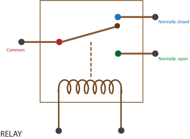
What is Relay?
The relay is controlled device which opens and closes contacts in order to effect operation of other devices in the same or another electric circuit.
• The relay is used in circuits with lower ampere capacity i.e. Max. 20A. • They are smaller in size. • They have at least two NO/NC contacts. • They are used in control circuits, automation circuits, protection circuits and switching circuits.
Differences
Relays are on-off devices. Transistors can have their voltage drop varied.
Relays are far slower than transistors; typically 50ms to switch, and probably more. Some types of transistors can switch in picoseconds (almost 10 orders of magnitude faster.)
Relays are isolated. Transistors can be (e.g. SSR), but are often not.
Relays are electromagnetic and bring problems with them – for example, try building a relay computer with many relays. You will find that relays will interfere with each other in some cases. Transistors are not very EM sensitive. They do not emit much electromagnetic interference.
Relays consume a lot of current in the “on” state, most transistors do not.
It’s a very important skill to learn how to remote control a robot in the robotics area. Our current technology is capable of creating millions of different machines with more skills than any other being on our planet. Although the top computers cannot even be compared to the human brain in terms of autonomy, it is a fact that they could perform very efficient when they have the human brain as a driver.
This project’s machine, glove plus robotic arm, uses Xbee modules to establish a communication channel between the devices. The “Arduino wireless shield” allows the Arduino board to transmit wireless using ZigBee, with a very reliable and simple communication. The protocol could be applied to almost any device with a serial port. Point to point or multi-point networks are supported too.
The glove is fitted with flex sensors (2.2”) to measure the movement of the fingers. Flex sensors, also called bend sensors, measure the amount of deflection caused by bending. These sensors can vary largely in terms of their range of resistance, measured as the difference from nominal resistance to resistance at full deflection.
One side of the sensor is printed with a polymer ink that has conductive particles embedded in it. When the sensor is straight, the particles give the ink a resistance of about 30k Ohms. When the sensor is bent away from the ink, the conductive particles move further apart, increasing this resistance (to about 50k). When the sensor straightens out again to his original state, the resistance returns to the original value too.
The below figure shows the block diagram for the glove part, device 1. The sensor measures the fingers position and through the Xbee module which is attached on the Arduino board transmits the information and waits for the device 2 to receive it.
Jointed arm robots are suitable for a wide variety of industrial tasks, ranging from welding to assembly and this is the main reason why I decided to build and remote control a robotic arm. Now there only two decisions left to make it possible, what kind of material is the best possible option for the body and the base and which motors suits the project’s needs.
The best material to build a small robotic arm is aluminum. Aluminum arms are strong, stable and cheap. I have found individual parts to buy online, these parts have numerous mounting holes which helped me to make a custom robotic arm using standard servo motors. Finally servo motors can be tricky, I have used one analog servo motor for the base, to rotate 360° and three digital servo motors for the joints and the claw. Digital servos can be extremely accurate but more expensive rotating usually 90° or 180°. Both types are useful but both of them have to be strong enough for their job. Keep in mind that for this type of arms, some servos have to lift others too. That’s why I had to calculate the amount of torque we would need. You must make sure that the motor can not only support the weight of the robot itself, but also what the robotic arm will carry when its stretched out to its maximum length.
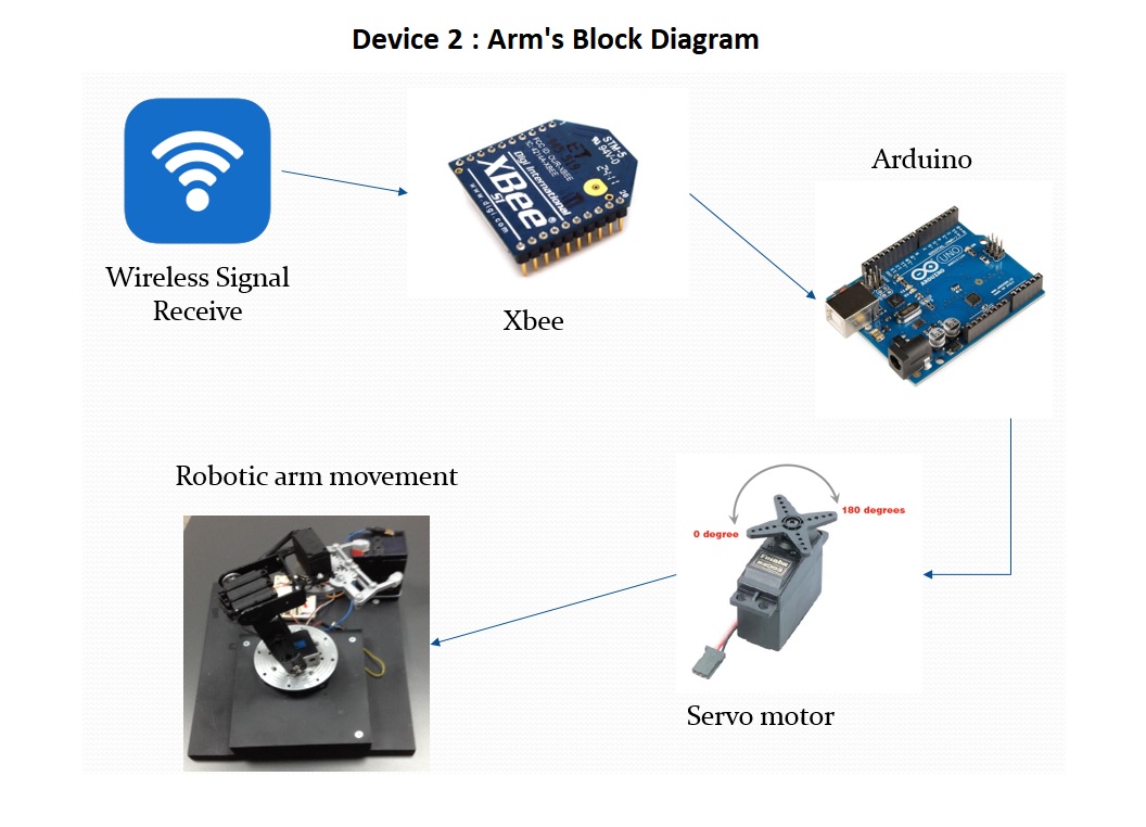
The below figure illustrates the robotic arm’s block diagram. After the information has been received by the device 2 with the use of the Xbee module attached to the second Arduino, the controller translates it into a movement for the appropriate servo motor, according to the finger move. The result is the movement of the robotic arm.
Arduino is an open source board with which you can easily build robotic and automation project without any deep knowledge of programming.
It contains an ATMEL chip which works as a processor, interfacing with analogue as well as digital I/Os. As analogue inputs one can use a variety of sensors and as outputs LEDs, servos, relays etc. Sometimes in order to receive the input signal it is necessary to use a special equipment that allows the input to reach the processor. This equipment is called a shield and usually it is adjusted on the top of the board (Wi-Fi Shield, Motor Shield, Ethernet Shield, SD Shield etc).
There are different boards with different specifications (i.e UNO, Mega, Leonardo, Nano) and the user has to select the one according to his project needs.
The board is being programmed through the Arduino IDE tool with the use of a simplified C/C++ language.